| Deutsch English |
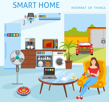
In the future, most electrical devices in your home will be controlled by microcontrollers and communicate wirelessly with each other.
IMPORTANT WARNING
|
When switching devices which are operated with the mains voltage of 230V, extreme caution is required. Contact with conductors and faulty switching can cause fatal voltage shocks |
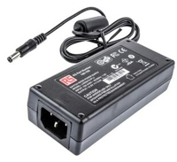
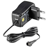
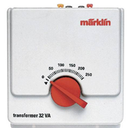
There is no danger when using devices which are operated with voltages below 30 V, e.g. low voltage LED lamps (usually 12V) model railways (Märklin 16V), low voltage aquarium pumps (12V), low voltage water valves (12V or 24V), etc. You can get the low voltage from a plug-in power supply or a closed electronic or coil transformer where you only have access to the low voltage.
Non-hazardous closed power supplies:
 |
 |
 |
Attention: Even the installation of a mains connection cable in non-encapsulated transformers is dangerous and may only be carried out under the supervision of a person with professional experience in handling high voltages. Before plugging in the mains voltage, the transformer must be securely closed.
Note: For direct switching of the mains voltage, a relay can be installed in a time switch housing. Instructions for professional users can be found under Installation of relay modules.
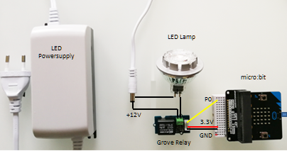
Example 1: Switching a 12V LED lamp or a 12V LED strip
A special LED transformer (stabilized voltage) is required for low-voltage LED lamps. The easiest way to switch the 12V supply is to use a relay module which is controlled via a digital port. However, the micro:bit can only switch currents up to max. 5 mA, which is not sufficient for direct control of relays. Therefore a cheap Grove relay module from Seed is used, with is controlled via a built-in driver (sources of supply: www.distrelec.ch, www.mouser.com, www.reichelt.de, various maker shops).
The relay is connected in series to the lamp and interrupts the 12 V supply when open.
For test purposes the following program switches the LED light on and off for 10 seconds. The relay input is connected to P0.
# SmarHome1.py from microbit import * while True: pin0.write_digital(0) delay(10000) pin0.write_digital(1) delay(10000) |
|
Explanations of the program code:
| pin0.write_digital(0): Switches P0 low and the relay opens | |
| pin0.write_digital(1): Switches P0 high and the relay closes |
You can switch on/off any low-voltage device in the same way.
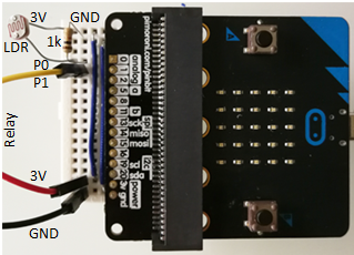
Example 2: Automatic lamp control
Connecting a light sensor and a resistor on port P0, you can build a simple light control system where the light is switched on automatically in darkness. The light sensor here is a LDR (Light Dependent Resistor), which is wired as follows:
# SmartHome2.py
from microbit import *

pin1.write_digital(0)

while True:
    v = pin0.read_analog()
    print(v)
    if v < 200:
        pin1.write_digital(1)
        display.show(Image.YES)
    if v > 250:
        pin1.write_digital(0)
        display.show(Image.NO)
    delay(100)
Explanations of the program code:
| if v < 200, if v > 250: Two different thresholds are used to switch the light on and off. This avoids flickering on/off switching, as the light level can fluctuate slightly. |