
| Deutsch English |
8. Installing LinkUp with ESP32 Coprocessor
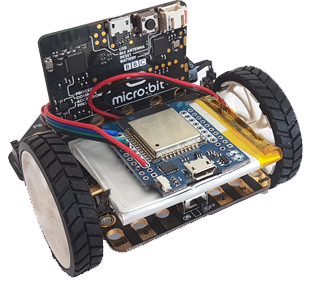
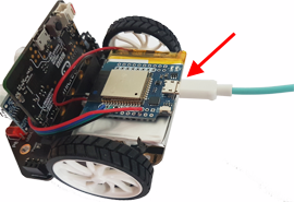
The micro:bit can be extended with a powerful ESP32 microcontroller which has an integrated WLAN system. The ESP32 is connected to the micro:bit via the I2C interface and attached to the Lipo battery with a double-sided adhesive tape. It functions as a I2C slave like an additional sensor and can start an WLAN access point with just a few commands or log on to an existing router and thus access the Internet. This allows the micro:bit to use typical cloud services or even start its own Web server, which is accessible from the Internet. The ESP runs its own firmware that is completely transparent to the micro:bit programmer who just has to know a few functions of the module linkup that implements a simple communication protocol.
|
 |
Additional hardware components (source of supply: www.bastelgarage.ch)
• |
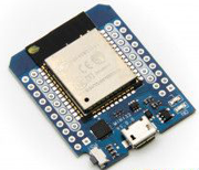
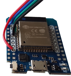
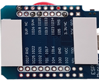
WEMOS ESP32 MiniKit (There are cheaper clones, for example. from Aliexpress MH-ET LIVE D1 mini ESP32) |
 |
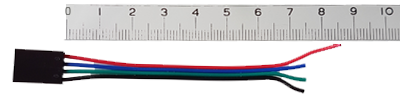
| • | 4-wire connection cable(jumper cable Dupont) or 4 single cables female-female (20 cm) |  |
• |
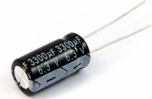
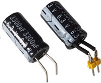
Electrolytic capacitor 3300µF/6.3V. Length 20 mm, diameter 10 mm
|
 |
|
|
 |
How to proceed:
1. |
Cut the cables to the correct length. The red cable is about 8.5 cm long, the other cables 1 cm shorter. (The colours serve as orientation only) |
 |
|
|
Strip all cables at the end about 3 mm with a Stanley knife or a stripping tool (do not damage the strands). |

|
|
 |
 |
|
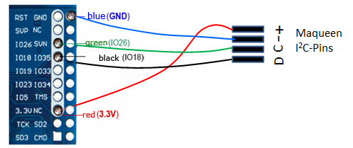
Wiring diagram: |
|
4. |
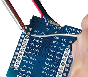
Apply two small strips of double-sided adhesive tape to the back side. |
|
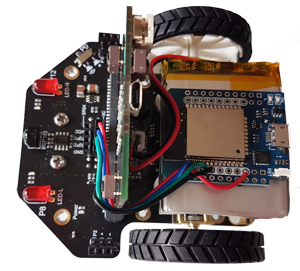
5. |
Fasten the ESP32 board oo the Lipo battery, pull the cables around the micro:bit and plug them in the I2C connector. Be careful about the polarity (consult the wiring diagram).
|
|
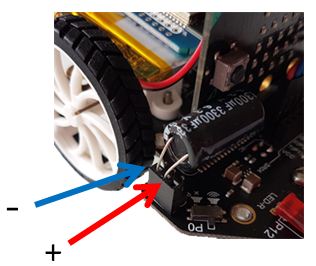
6. |
When plugging in, make sure that the polarity is correct (marked on the capacitor and next to the socket). |
 |
7. |
Installing the firmware:
|
|
|
• | You can check if the ESP is detected correctly |
|
• | In TigerJython select ESP32 under Tools/Devices and enter this port (e.g. COM3) |
8. |
Test ATTENTION: If the ESP is not in use, it switches off automatically after 5 minutes in order to save power (the blue LED no longer flashes). To reactivate it, press the reset button of the ESP. This is also used to reset the ESP from a blocking Web server state back to command mode. Test for advanced users:
|